The Doghouse Brew Rig (brutus style) - By 2nobledogs
What is the Doghouse you ask? Well, it’s a single tier brew stand based loosely on the Brutus 10 and like the Brutus it is a fully automated system. I do want to acknowledge and thank everybody that helped throughout this whole process. Plenty of ideas and help came from the folks at www.homebrewtalk.com.
I had several design goals in mind when I started. First, it needed to be fully automated (duh…). Second, it needs to be fully self-contained when stored away. Third, it needs to be maneuvered easily. Fourth, it needs to fit in my truck. And lastly, it needed to have adjustable burners.
So, what do you need to know about automated brewing before you start building a brew rig? Nothing. I didn’t know a thing about it when I started. Everything you need to know is on the internet. You just have to look for it.
All automated brew rigs have four basic components/systems. 1) Frame, 2) Gas, 3) Plumbing, and 4) Electronics.
Frame Construction
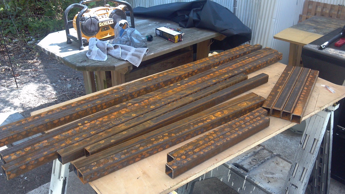
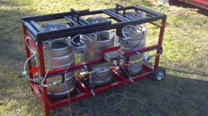
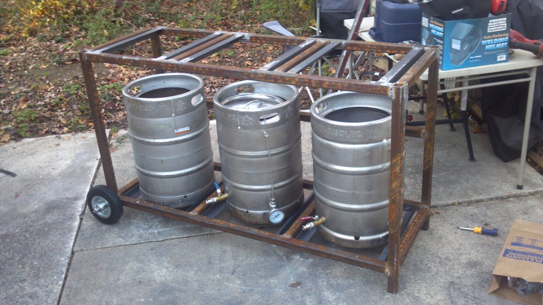
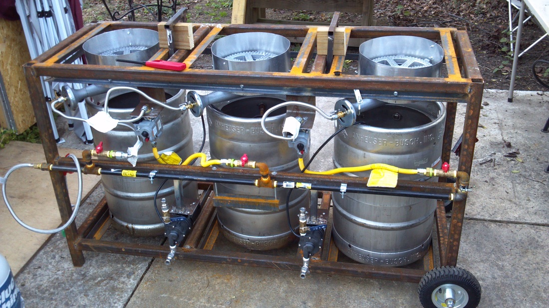
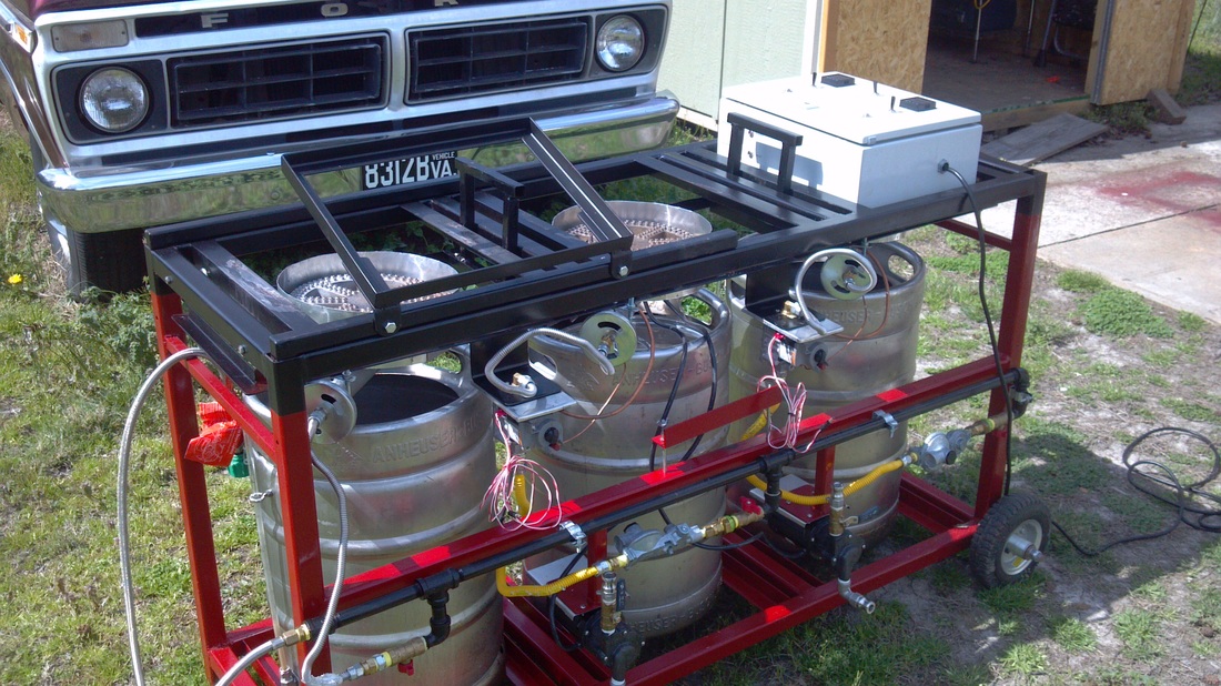
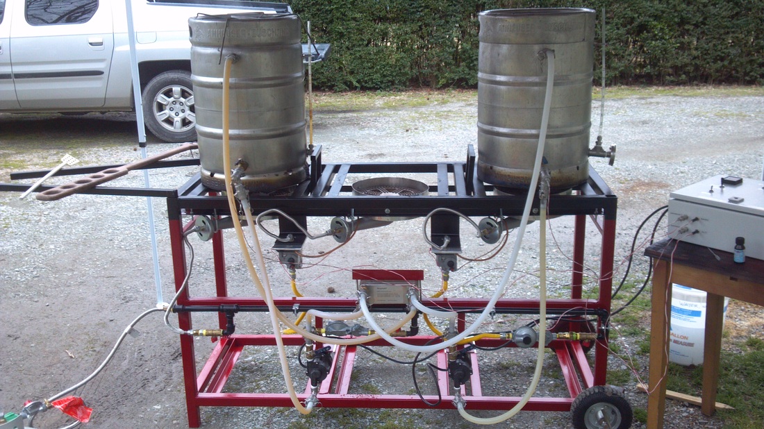
My frame is primarily constructed out of 1 ½” square steel tubing a got from a welder friend of mine. The steel I used is “mild” steel. It is relatively inexpensive and easy to weld. It’s also fairly easy to find. The design allows me to store all my keggles underneath when not in use. It also has pneumatic wheels on one end so it can be maneuvered like a wheel barrow from the storage shed across the yard to the driveway where I brew. The burners are also mounted on a separate rack that can be adjusted easily.
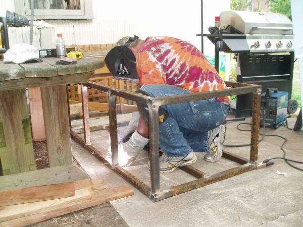
I had never welded before so this was a learning experience for me. I picked up a simple wire feed welder from Harbor Freight for about $100 and started making sparks. I was happy to learn that welding is not that difficult. Don’t get me wrong…making pretty welds is very difficult but if you’re not too concerned about what the weld looks like it’s pretty simple. Keep in mind that I used mild steel not stainless steel. If you use stainless you’ll need a different type of welder. Make sure you cut all your pieces square and clean up the burrs before you start your weld. It also helps if you grind a small bevel on the ends. If you have one, use a right-angle clamp. This will ensure that your rig goes together straight and true. Once you get done with a weld you will want to clean it up and grind it down as you go. Doing this will keep you from having a very long day when you get ready to paint. You will also want to prime your steel immediately. If you don’t it WILL rust and you’ll have another long day of cleaning and scraping when it comes time to paint. I know this from firsthand experience.
The Gas System

Next, let's discuss the different components of the gas system and how it all goes together. The first thing you should know is ALWAYS BE SAFE! Putting the gas system together is not difficult but if you are not completely comfortable tinkering with gas lines you may want to get some assistance. This post assumes that the main frame and the burner mount frame has already been assembled. If not, refer to back to part one of The Doghouse Brew Rig Build here.
The gas system is made up of components that will transfer the gas from the tank to the burner. Sounds simple, right? Well, not exactly but, if you keep that thought in mind it helps you visualize how things need to go together.
Now that you have decided to tackle the gas system you need to decide whether you are going to use a combination of High pressure and Low pressure OR just use all Low pressure. This system utilizes furnace valves to regulate the burners and these furnace valves only operate under low pressure. I used both high pressure and low pressure (high pressure for the boil pot and low pressure for the others) on my system. I wanted high pressure on the boil pot so I could get it to a boil faster. If you use an all low-pressure system some of the components listed below are not needed. I could get into the differences between high and low-pressure systems, but I’ll save that for another post. You just need to decide which one you want to use.
Components
There are many variations in the components that you can use. For this post I’m only going to discuss what I used on the Doghouse which is a combination high and low pressure system.
Gas System:
There are many variations in the components that you can use. For this post I’m only going to discuss what I used on the Doghouse which is a combination high and low pressure system.
Gas System:
- ½” Black Pipe and fittings
- 2 – 24” length
- 1 – 6” length
- 3 – 2” length
- 2 – ½” x ½” Tees
- 4 – ½” 90° Bends
- 1 – High Pressure regulator hose w/ tank connection
- 3 – ½” Gas ball valves
- 2 – Low Pressure Regulators
- 3 – BG-14 Banjo Burners
- 2 – Low Pressure Orifices (converts burners to low pressure)
- 5 – Flexible gas lines
- 2 – Honeywell Furnace Valves
- 2 – Honeywell Pilot Lights
- 2 – Honeywell Termocouples
- 5’ – ¼” flexible copper tubing
- Variety of brass fittings to connect everything up
- RectorSeal (dope) or Teflon tape (made for gas)
Assembly
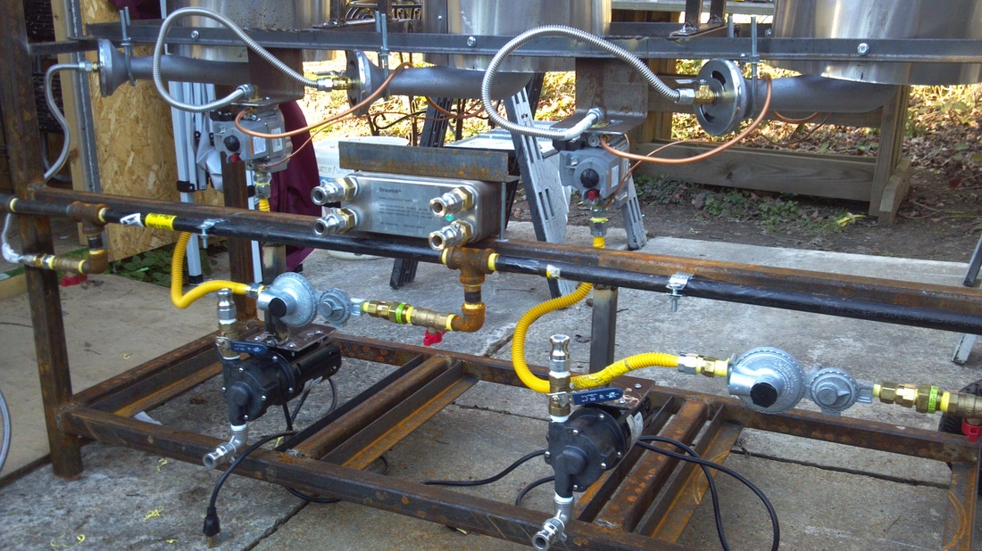
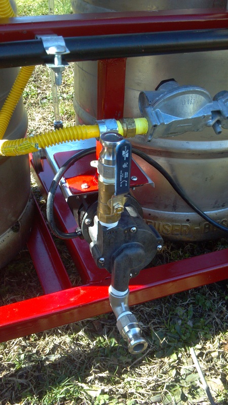
The first step is to assemble the gas manifold (I’m sure I probably don’t need to point this out but I’m going to anyway, USE RECTORSEAL OR TEFLON TAPE AT ALL OF YOUR CONNECTIONS). It is constructed out of ½” black pipe that you can pick up at any hardware store. Do not use the gray or galvanized pipe. Assemble the pieces so you have a fitting attached to one end to accept the gas line from the tank. Then connect the remaining pipes and fittings so you have 3 outlets to feed the burners. Attach a ½” gas ball valves to the black pipe at each outlet. Now you want to attach a low-pressure regulator to the 2 outlets that will ultimately attach to the burners under the Hot Liquor Tun (HLT) and the Mash Liquor Tun (MLT). One my system they were the middle and far right burner. Now connect a flexible gas line to each low-pressure regulator and one to the outlet that will go to the burner for the boil pot (far left on my system). Connecting all this up can be a bit confusing because of all the different fittings and thread sizes involved. Don’t let it bog you down. You will be using a ¼”, 3/8”, or ½” fitting. With either a flared end or NPT thread. The easiest thing to do is lay out each of your components and then draw a rough sketch that illustrates the sequence that they will be connected. Label each end of the component as to what size fitting is needed to make that connection.
Then you can take that sketch to Lowe’s or HD and get the folks there to assist you. I found that they were always more than willing to help and once you told them it was for a brew rig they made it their personal mission to make sure they got you what you needed. One thing to note: if you use appliance gas lines as I did (yellow lines on my rig) they will come with several fittings. They will also come with a safety valve which will keep the gas from backing up in the system. Seems like a good idea right? So, when you lay out the components you probably already have a few of the fittings that will work. One more thing on the appliance gas lines, the safety valves only work on the low-pressure lines. They will not work for the boil kettle burner.
Now you need to change out the high-pressure orifices to low pressure orifices on your HLT and MLT burners. Once you’ve completed that, connect the flexible gas line from your manifold directly to the burner orifices. Now you can connect your propane tank to the manifold using your high-pressure regulator line. Notice we have not connected the furnace valves yet. The reason for this is because those valves will not operate properly without the controller telling it what to do. The controller is part of the main control panel which we will get into in a future post.
Check for Leaks
Now we need to check for leaks. With all the ball valves closed on the manifold, slowly open the propane tank valve. This will fill the manifold with high-pressure gas. Listen and smell for any leaks. If you do smell or hear something try to isolate it by sound. If that does not work spray soapy water around the joints and look for bubbles. Once you’ve isolated the leak, take that joint apart, rewrap it and tighten it back up. Repeat that process until the situation is corrected. Once the manifold has been check, move on to each individual outlet. Open each ball valve one at a time and listen/smell for leaks. Correct as needed. This is a little more difficult on the boil pot burner because there is no valve on the high-pressure orifice as there are on the low-pressure orifice. You will need to use soapy water as soon as you open the ball valve. At this point, you should not have any leaks all the way to the burners. Now you can test the burners themselves. Again, open each ball valve one at a time and fire the burner. You should see a blue flame about 1.5” to 2” coming out of the low-pressure burners and a 1” blue flame blasting out of the high-pressure burner. You may need to adjust the air openings to get the proper flame.
Now attach the manifold to the main frame. I used single screw conduit hangers from Lowes.
Furnace Valve and Pilot Assembly
Once you are satisfied that everything is working properly to this point you can remove the burners from the gas lines and prepare to connect the furnace valves. My furnace valves are connected to the “burner frame” as opposed to the actual brew rig frame. You can do it either way just keep in mind you want to minimize the stress on the gas line connections into the valve itself. To me it made more sense to keep the relationship between the valve and burner constant in the event I needed to adjust the height of the burners.
The furnace valves I used were Honeywell. They are set up to be used on a natural gas system. No big deal, these are easily converted to LP gas using the included conversion kit. Make sure you follow the instruction that come with it but it is almost as simple as replacing a light bulb. Now your valve is set up but don’t attach it to your frame yet. You still need to attach the pilot light and thermocouples.
The pilot light and thermocouple need to be attached to the burner so it can fire properly. The pilot light I used comes mounted on an “L” shaped bracket. I straightened the bracket out and then mounted it on the bottom of the burner with the light itself located in between to openings on the burner. I used tiny self-tapping screws for the connection. I also coated the threads with Rectorseal.
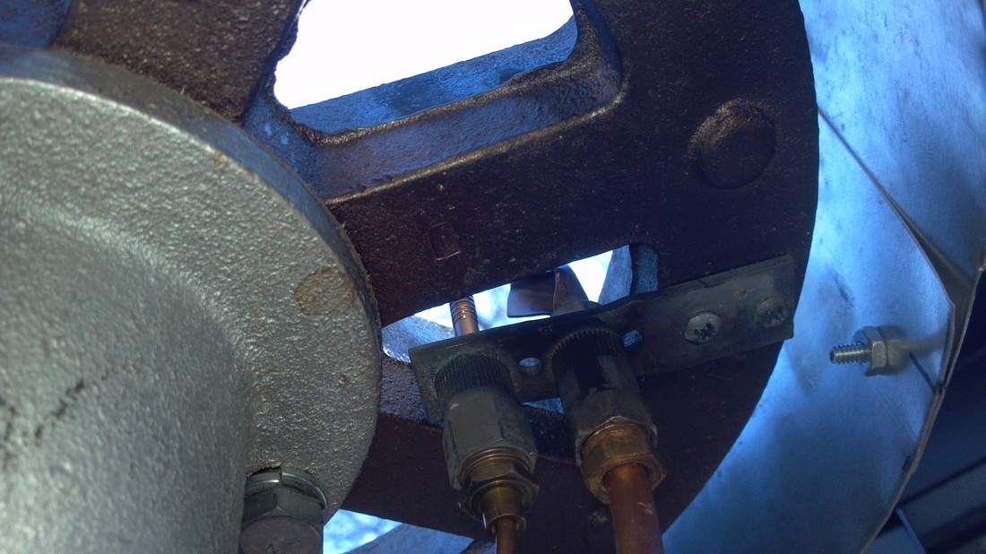
If you have not already mounted the burners, go ahead and mount them to the burner frame. Then place the furnace valves in the general location of where they will be mounted on the frame. Cut a piece of ¼” flexible copper line about 18” long (this may vary on your rig) to connect the pilot light to the furnace valve. Make sure not to damage the end. De-bur and clean the ends and connect to the pilot light with the compression fitting included with the light. Now, very gently, bend/form the line around the burner and back to the furnace valve being careful not to crimp the line (pipe benders can be used for this step). Connect the line to the furnace valve using the compression fitting included with the valve. Next, uncoil the copper line attached to the thermocouple and attach to the furnace valve. This has very specific tightening instructions so make sure you follow them precisely or your valve won’t work. I found this out the hard way. Now you can mount the valve to the burner frame.
At this point, you should have you manifold mounted to the main frame, and the burners and furnace valves mounted to the burner frame. Now just connect the remaining flexible gas lines and you're there! Woohooo!
At this point, you should have you manifold mounted to the main frame, and the burners and furnace valves mounted to the burner frame. Now just connect the remaining flexible gas lines and you're there! Woohooo!
The Control Panel
For this section, I’m going to discuss the components of the control box. The control box is what automates your system. The components of the box send signals back and forth to your furnace valves (described in Part Two), which in turn open and close to fire the burners. This keeps the strike water and mash at the desired temperature. Keep in mind that if you are going to a direct fire type of mash tun you must recirculate your mash to keep it from scorching.
As with the gas system, there are probably many ways to put the control panel together. For this post, I’m going to focus on what I used to build mine.
To build the control box you will need:
• 1 – 10”x6” Electrical Enclosure (my was much larger than 10”x6”, but I was fortunate enough to get it as a gift from my good friend over at 17 Apart)
• 2 - PID Temperature Controllers – Auber SYL-2362
• 2 – Panel mount RTD connectors
• 2 – RTD Sensors
• 3 – Switches (Single pole single throw) Main Power, and Pumps
• 2 – Switches (Single pole double throw) Furnace Valves
• 1 – 120v-24v Transformer
• 2 – Terminal Strips
• 2 – Jumpers
• 1 – Standards 110v power receptacle
• 1 – 15’ Extension cord
• Various wire connectors
• Electrical wire
|
|
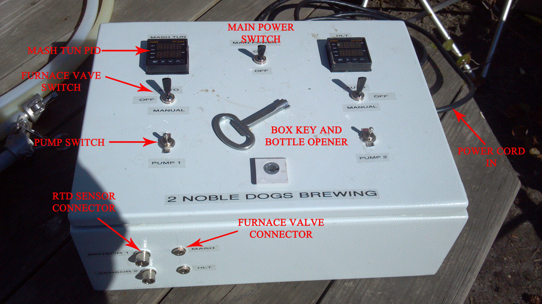
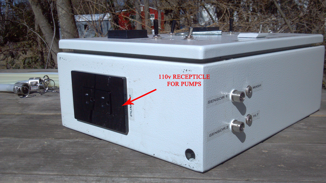
Once you’ve collected all of the components you are ready to get started with the assembly. Start by determining how you want your box to look. Then layout the component locations and cut the openings. This is easily done with a jig saw and a metal cutting blade. Inside the control box, you have a few things happening. First you have a 110v supply line coming into the box. That line then gets split into a 110v side and a 24v side through the use of the transformer. The 110v side powers the pumps and the PIDs, while the 24v side sends power to your furnace valves. Also inside the box, the PIDs receive a signal from the RTD temperature sensors and then send a signal back to the furnace valves telling them to open or close.
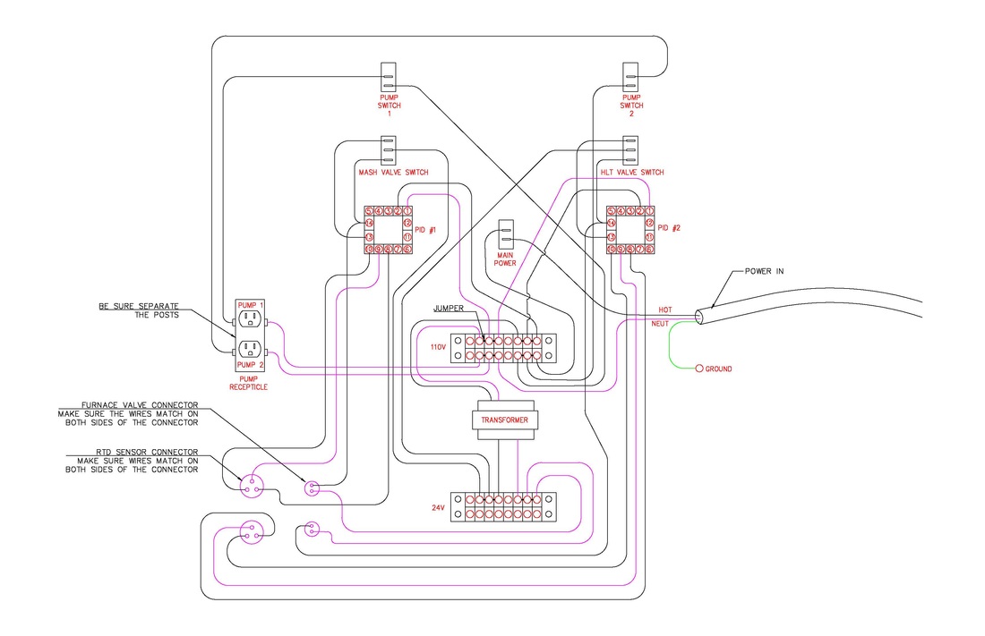
Trying to explain how this all goes together is quite difficult. Instead, I’m going to show you with a few diagrams. They say a picture is worth 1000 words right? Also, keep in mind I’m no electrical guru so I have no idea how to draw up a real electrical schematic. I had to enlist my awesome wife to put these images/video together. If you find this information helpful make sure you let her know in the comments below . I know she would appreciate it.
Trying to explain how this all goes together is quite difficult. Instead, I’m going to show you with a few diagrams. They say a picture is worth 1000 words right? Also, keep in mind I’m no electrical guru so I have no idea how to draw up a real electrical schematic. I had to enlist my awesome wife to put these images/video together. If you find this information helpful make sure you let her know in the comments below . I know she would appreciate it.
Below is a wiring diagram for the panel. Again, I’m not an electrician so I apologize for not using the appropriate terminology and symbols. It should be pretty self explanatory but feel free to ask questions. Also, you can click on the image to enlarge it.
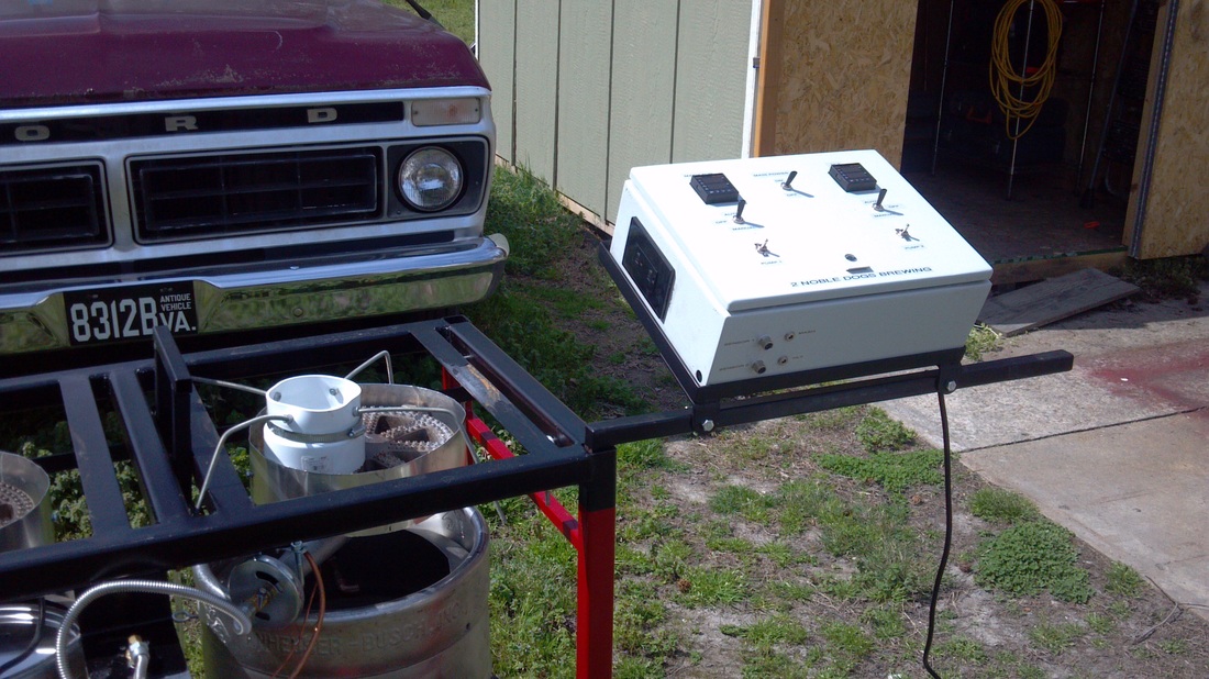
Once I completed the panel I had to find a way to mount it on the frame. Seems simple, right? But, remember I need everything to stow away neatly so I could not have anything permanently protruding from the frame. My solution was to build a frame and then bolt it to one of the removable handles. By doing this the handle still acts as a “wheel barrow” handle, then acts as a panel mount, and then stores away neatly at the end of the brew day.
|
|
|
Finally, you will need to set your PID settings. You can follow the instructions that came with the PID but I found them somewhat confusing. Mine are set as follows:
inty – P100
outy – 4
HY – 3
atdu- 0
psb – 0
rd – 0
corf – 1
This should get you going on your control panel, but, keep in mind that this is a broad overview. Make sure you follow the instructions of your specific components.
inty – P100
outy – 4
HY – 3
atdu- 0
psb – 0
rd – 0
corf – 1
This should get you going on your control panel, but, keep in mind that this is a broad overview. Make sure you follow the instructions of your specific components.
The Plumbing
I’m sure this does not need to be pointed out, but basically your plumbing system moves your strike water and wort from one vessel to the other. This system is what keeps you from having to lift up those heavy 10-gallon batches. I don’t know about you guys, but I’m not the young buck I used to be. Those batches get heavy…
So, the components that make up the plumbing system are as follows:
So, the components that make up the plumbing system are as follows:
- 3 – Keggles/Kettles of your choice
- 2 – Food Grade Pumps (March 809)
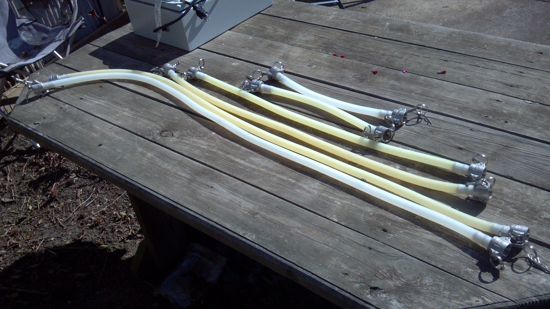
- 21′ – 1/2″ High Temp Silicon Tube
- 5 – 1/2″ Ball Valves (Brass or SS)
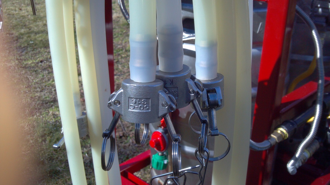
- 14 – 1/2″ Female Cam-Locks w/1/2″ Barb
- 9 – 1/2″ Male Cam-Locks w/1/2″ Male Thread End
- 6 – 1/2″ Male Cam-Locks w/1/2″ Female Thread End (4 are used for the plate chiller)
- 2 – 1/2″ SS Tee
- 2 – 1/2″ Male to 3/8″ SS reducer
- 2 – 1/2″ 90 Degree SS Street Elbow
- 5′ – 1/4″ Coiled Copper Tubing
- Various 1/2″ copper fittings
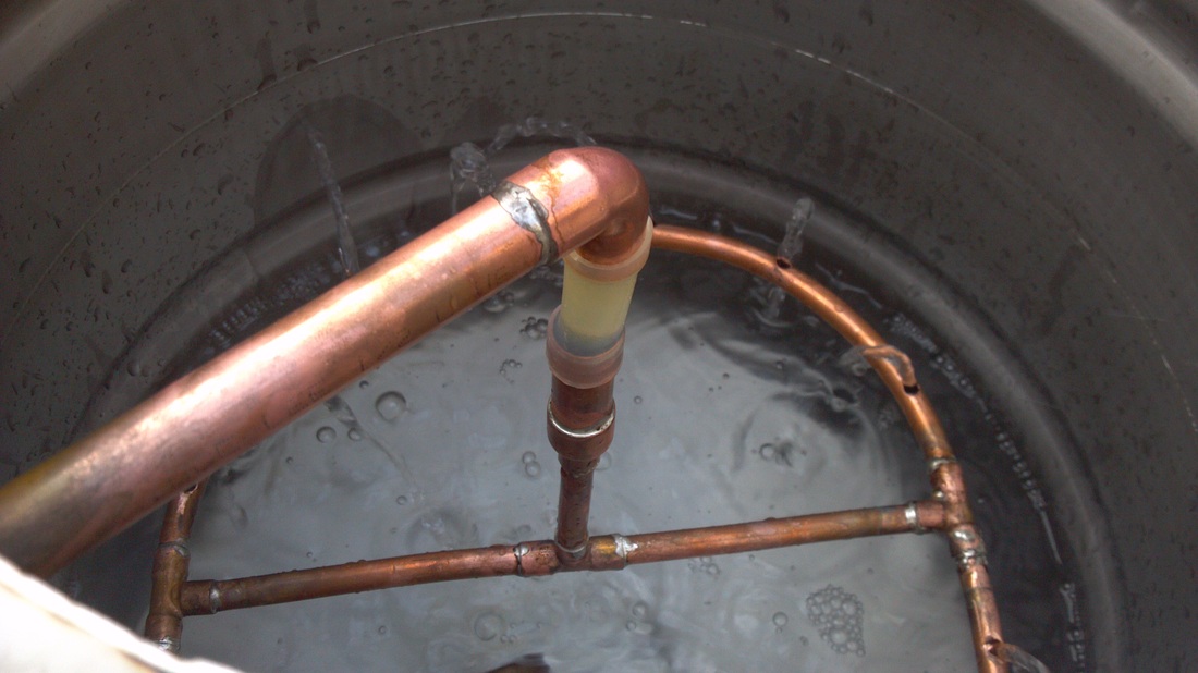
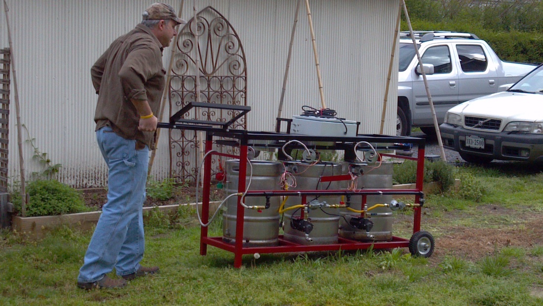
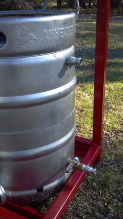
The first thing you want to do is set up you keggles/kettles. You probably already have these set up, but you need to make sure that in addition to the typical 1/2″ ball valve you also have a return fitting near the top to allow for proper recirculation. You can see this in the picture above. You also need to have one of you keggles set up for to be a mash tun. This means you will need to have some type of false bottom with pick up tube. In order to recirculate you mash you will also need to fashion some type of sparge arm to reintroduce your wort back into the grain bed.
My sparge arm was made from 1/4″ copper with small holes drilled around the top of it. The silicon tubing you see in the picture above is used to keep the sparge arm at the correct height over your grain bed. I keep mine positioned about 1″ below the top of the grain. This arm disperses the flow back into the grain bed and helps prevent channelization. The length of the tube can be changed depending on the amount of grains you have in the tun.
The HLT and the boil kettle should be set up similarly to what you probably already have. Both need the valve and top return along with a dip tube. My HLT and brew keggles also have sight glasses built in. I do not have a sight glass on my mash tun simply because I already have one on the HLT. If you know how much is coming out of the HLT then you know how much is going into your mash.
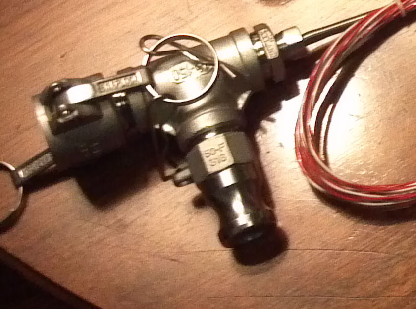
So, now that your keggles are set up you need to build the Tees. The tees contain the temperature sensors to are wired to your PID’s (See electrical system post HERE). Make sure you are using teflon tape at all your connections. These are critical components to the whole system working properly.
My sparge arm was made from 1/4″ copper with small holes drilled around the top of it. The silicon tubing you see in the picture above is used to keep the sparge arm at the correct height over your grain bed. I keep mine positioned about 1″ below the top of the grain. This arm disperses the flow back into the grain bed and helps prevent channelization. The length of the tube can be changed depending on the amount of grains you have in the tun.
The HLT and the boil kettle should be set up similarly to what you probably already have. Both need the valve and top return along with a dip tube. My HLT and brew keggles also have sight glasses built in. I do not have a sight glass on my mash tun simply because I already have one on the HLT. If you know how much is coming out of the HLT then you know how much is going into your mash.
So, now that your keggles are set up you need to build the Tees. The tees contain the temperature sensors to are wired to your PID’s (See electrical system post HERE). Make sure you are using teflon tape at all your connections. These are critical components to the whole system working properly.
|
Now, you need to get your pumps installed. I used the March 809 pumps. They seem to be the most common. Mine hang from the frame with a sheet of aluminum as a splash guard. They plug directly into the panel box and are controlled with the switches you wired up in part three of the series. When you mount the pumps make sure the inlet is on the bottom and the outlet is on the top. Gravity will force fluid into the pumps and push the air out of the top. This helps prime the pump.
|
|
The last thing you need to do is cut your hoses to length and start brewing. If you are using a plate chiller you will need 6 hoses. Kettle —>Pump—>Chiller—>Kettle x 2.
|
|
How It Works
Finally, let's talk a little about how all the systems work together to produce that wonderful libation we refer to as BEER. In earlier posts, we discussed the frame, the gas system, the electrical system, and finally the plumbing. I have to admit that when I finally got all of this put together and working properly I felt a little like Gene Wilder in the movie Young Frankenstein. “It’s Alive!”
Sorry…I couldn’t resist.
Now that you have the rig set up where you are going to brew, attach the gas to the regulator hose and open it up completely. Open up the ball valves that feed the furnace valves and turn the switch on the furnace valve to “pilot”. Hook up your control panel to a power source and turn on the main power switch. Connect the furnace valve wires and turn on both switches for the mash tun and HLT. Now light your pilot light following the lighting instructions that came with the furnace valves. These will stay lit until you get to the chilling stage. It is important to light your pilots before you put your kettles over the burner and fill them with water. Once you’ve done that it makes it very difficult to reach the pilot light.
Ok, your pilots are lit and you set your kettles over the burners. Now attach the “sensor tees” to the outlet valves on the kettles and connect the sensor wires to the control panel. Once you do this your PIDs will start to register the temps of the sensors. You can set the target temperatures in both PIDs at this point. DO NOT turn on the main control switch located on the furnace valve yet! (Ask me how I know this….). Fill your HLT with strike water using your preferred method. Now that you have some water in your kettle, you can turn on the main control switch on the furnace valve for the HLT only. That burner should fire once that has been done. Now hook up one hose coming from the tee and attach it to the inlet on one of your pumps. Hook another hose from the outlet of the pump and connect it to the upper intake fitting on your HLT. Plug in your pumps, open the valves, and turn on the pump you have hooked up. This circulates the water over the sensor so it gives you an accurate reading on your PID. Once it reaches the target temp the burner will shut off and then fire intermittently to keep the temperature where it needs to be.

When your strike water hits the desired temperature its time to transfer it to the mash tun. This is done simply by moving the upper hose from the HLT to the mash tun. Make sure your pumps are OFF before moving anything. Once the hose is moved you can restart the pump and dough in as you normally would. Once you are doughed in turn off the pump and attach the recirc/sparge arm. Attach the second sensor tee to the mash tun and hook everything up to the second pump just as you did for the HLT. Place the upper hose back on the HLT. Now you can open up your valves and start to recirculate your mash. Open up the main control on the second furnace valve at this point. This burner may or may not fire right away depending on the heat loss during the dough in. Keep the mash moving to prevent scorching but don’t pump it too fast. This should recirculate slowly so you’re not constantly churning up your grain bed.
Once your mash is complete transfer it to the boil kettle. Sparge using your preferred method. I fly sparge VERY slowly. This helps keep my efficiency at an acceptable rate (usually around 70-73%). Once you have everything in your boil kettle turn off the power to both furnace valves and the gas ball valves. Now open the ball valve to the BK burner and fire that bad boy up. You will need to regulate this with the regulator hooked to the LP tank. keep an eye on the LP tank. It may start to freeze up. If this happens just place it in a tub with warm water.
Now, her’s the cool part. By using both pumps and recirculating your wort and chilled water you are able to crash your temperature in a fraction of the time it normally takes. Because a picture is worth a thousand words, attach your hoses in the configuration shown in the picture below. You can click on the picture to enlarge it.

Now fill your HLT with tap or well water and start to recirculate both kettles through your plate chiller. This will pretty quickly knock down your wort temp to about 150 degrees. Your PIDs will be monitoring the temps now. Once you get to this point or below you need to remove the water from the HLT and replace it with fresh tap or well water AND 3 or 4 bags of ice. Your temps will start to plummet. NOTE: keep an eye on your temperature or it will blast right by your target pitching temperature. Once you're chilled move the wort to your fermentor and get to cleaning. This process is no different than your normal cleaning process except you need to circulate some PBW through the one dirty pump and plate chiller. I will also pour boiling water through both before the next brew session just in case.
So, that’s it. It’s a lot of words, but the process is really pretty simple.
Clay
So, that’s it. It’s a lot of words, but the process is really pretty simple.
Clay
If you have any questions about this amazing build, shoot over to 2 Noble Dogs Brewing and contact Clay. I'm sure he would be happy to answer any questions you have.
